An overview is given here over the orthodox theory of single electron tunneling
networks. Not everything will be derived in detail, rather this is intended to be an
easy to understand and concise summary.
1 The Capacitance Matrix
A SET-networks consists of normal islands or charge nodes, and of potential nodes or
voltage sources. All nodes are connected to each other by either pure capacitors or by
the capacitances associated with tunnel junctions.
In this outline, voltages and charges on the nodes are specified by n-dimensional
vectors
 | (1) |
which are divided into c-dimensional sub-vectors for the charge nodes, and
v-dimensional sub-vectors for the voltage nodes. The vector Nc denotes
the number of electrons on the charge nodes and Nc0 are the fractional
offset charges. The quantity e = 1.6022 × 10⁻¹⁹C is the (positive) electron
charge.
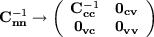
Charges and voltages are related to each other via the capacitance matrix Cnn
which is accordingly divided into four sub-matrices,
 | (2) |
The diagonal elements Cii of the capacitance matrix are the total capacitances of
the corresponding nodes,
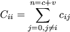 | (3) |
Here, cij are the capacitances between the nodes i and j, no matter whether they are
charge or voltage nodes, and ci0 is the capacitance of island i to ground. The
off-diagonal elements of the capacitance matrix are minus the capacitances between
the corresponding islands i and j,
 | (4) |
The voltages Vv on the voltage nodes are known. Voltage nodes can be thought
of having very large capacitances to ground and, as a consequence, a very large
amount of charge on them,
 | (5) |
Since the capacitance to ground is very large, almost all of the charge will be
polarized on it, and this determines the voltage on the island in respect to the
zero ground potential. If an electron tunnels to or from the voltage island,
and the charge on the ground capacitor is changed by about one electron
charge, the voltage across the ground capacitance will remain practically
unaffected.
The voltages Vc of the charge nodes depend on the charges Qc of the charge
nodes and on the voltages Vv of the voltage nodes. From (2) the important relations
 | (6) |
and
 | (7) |
can be deduced. Here, Ccc - 1 is the inverse of Ccc. Because of (5) the inverse of the
total capacitance matrix goes to
 | (8) |
2 The Electrostatic Energy
Because of (5) the total electrostatic energy E of the whole SET-network,
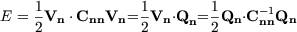 | (9) |
is infinite. Subtracting the infinite contributions one gets the electrostatic energy
stored on the capacitances between the charge nodes, the capacitances between
charge nodes and ground, and the capacitances between charge nodes and voltage
nodes,
 | (10) |
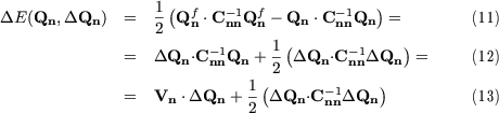
However, it is not so much the electrostatic energy itself, but the change of
electrostatic energy, that is of interest, if the charge state of the system
changes from an initial value Qn to a final value Qnf = Qn + DQn. Starting
from (9), the corresponding change in electrostatic energy can be written as
Here, Vn are the voltages for the initial charge state, which can be calculated
according to (7).
3 Tunneling
For the case when one single electron tunnels from one node i to another node j, the
vector DQn is zero everywhere except for two elements where it is plus and
minus e, respectively. The change in electrostatic energy the simplifies to
 | (14) |
If one of the nodes i or j is a voltage node, this simplifies with (8) even further to
 | (15) |
or
respectively.
The tunnel resistances Rij of the tunnel junctions between the nodes i and j have
to be considerably greater then the quantum resistance RQ = h/e2 = 25.8 kW, in
order that the charges on the islands be well defined.
If one knows the temperature T and the change of total electrostatic energy DE
of the network, the probability Gij of tunneling per unit time can be evaluated with
 | (16) |
At zero temperature the probability for tunneling is non-zero only if the change in
electrostatic energy associated with it is negative,
This is the case if the difference in voltages V j - V i between the two islands is bigger
than a critical value 
 which is independent of the charge state
of the system.
which is independent of the charge state
of the system.
If there are t tunnel junctions in a SET-network, then there are 2t possible tunnel
events, and the network is in a stable state, if none of the tunnel events is allowed at
zero temperature.
4 Stability Diagram
One can ask the question, if a certain charge state can be stable in principle, if one
adjusts the voltages on the voltage nodes accordingly, and for what region of the
voltage boundary condition space this is the case.
For that, the corresponding change in electrostatic energy for every one of the 2t
possible tunnel events has to be positive. With (14) and (7) one therefore gets 2t
inequalities which have to be fulfilled. For tunnel events from one charge node to
another they are of the form
for tunnel events from a charge node i to a voltage source j they look like
and for tunnel events from a charge node j to a voltage node i
If one fixes the voltages on all but two voltage nodes q and r, this gives 2t lines in
the voltage boundary condition plane, each of which divides the plane into two
half-planes, for one of which the corresponding tunnel event is allowed and for the
other of which it is not. The intersection of all the half-planes for which
the tunnel events are not allowed is then the stability region for the state
Qc.