Numerical Methods
|
|
Numerical Methods | |
|
|
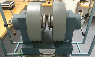
Bruker Magnet B-E 15
The electromagnet in the Magnet Laboratory consists of a Bruker Magnet B-E 15, and a Heinzinger PTN 125-40 magnet power supply. These can be used to generate magnetic fields of up to about 1 Tesla. The field strength depends on the current and the distance between the poles of the magnet (Air gap). This distance can be adjusted by turning the handles on the sides of the magnet. In the electromagnet, an insulated wire is coiled around a ferromagnetic core and a current through the wire creates a magnetic field according to Ampere’s law. The ferromagnetic core has a large permeability which increases the field by a factor of up to several thousand due to the alignment of the magnetic domains. The ferromagnetic core is a soft magnet with a low coercive field so that there is only a small amount of magnetic hysteresis. The magnet can be driven with a maximum continuous current of 30 A. The Heinzinger PTN 125-40 is a DC power supply that can provide currents up to 40 A so make sure to limit the current to 30 A. The magnet has two coils with a total resistance of 3 Ohm (1.5 Ohm each) so the voltage needed for maximal magnetic field is at 90 V. The magnet is water cooled and has to be cooled the whole time it is in use. Before using it make sure to open first the water drainage valve and then the water inlet valve.
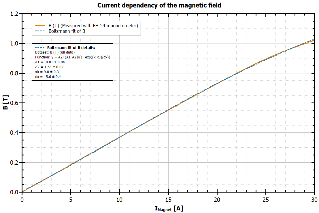
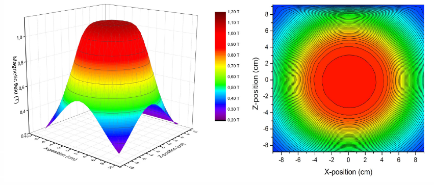
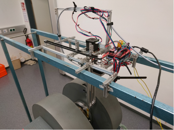
This figure shows how magnetic field depends on the current when the air gap is 5 cm. The magnetic field was measured with a Magnet Physik FH54 magnetometer. At a magnet power supply current of 30 A, a magnetic field of 1.03 T is generated. The relation between the magnetic field (magnetic flux density) and the power supply current is linear up to approximately 20 A. For larger currents, the relation is non-linear as the magnetization approaches the saturation magnetization. The magnetic field is not homogeneous inside the entire air gap, it is homogeneous (with a deviation < 1 %) inside a cylinder with a diameter of about 7 cm in the center and has a steep drop at the edges of the magnetic poles. The figures below show the homogeneity of the field and the set-up that was used to make this measurement.
Because of the ferromagnetic core, there is always a small remnant magnetic field of about 2 mT inside the air gap. The direction of this field depends on the direction that the magnet was last magnetized. Manual operationFirst open the water drainage valve and then the water inlet valve. Turn down the rotary knobs for the current and the voltage to zero and turn on the Heinzinger PTN 125-40 power supply by pressing the power switch. In manual operation mode the indicator light for local is on and the power supply is always ether limited by the current or the voltage that is set with the associated rotary knob, whichever is lower. This is indicated by the lights next to the knobs. Usually we want to set the current so the current should be the limiting quantity, so you can set the voltage to some higher value (by spinning the voltage knob a few times). Then slowly increase the current by turning the current knob. Changing the current through the magnet quickly can lead to significant inductive voltage spikes. This occurs, for instance, if a large current is flowing and the power supply is simply turned off. While there are diodes in the magnet to prevent damage from the voltage spikes, you should always change the current slowly (less than 1 A/s). The maximum continuous current the Bruker Magnet can withstand is 30 A, so do not use values higher than this. To shut the magnet down, reduce the current slowly (less than 1 A/s) until the current is zero. Then turn the voltage knob to zero and turn of the power switch. Close the water inlet valve and then the water drainage valve. The direction of the magnetic field can be changed by rotating the magnet. Be very careful that the cryostat is not damaged as the magnet is turned. Only turn the magnet if the cryostat is exactly vertical or completely out of the magnet. SafetyDepending on distance, magnetic fields may influence the function of technical devices. This especially refers to cardiac pacemakers (Herzschrittmacher). Persons with pacemakers must not be exposed to magnetic fields. The upper end of the voltage range of the Heinzinger PTN 125-40 is at 125 V which is just high enough to exceed the extra-low voltage range (< 120 V DC, < 50 Vrms AC), which carries a low risk of dangerous electrical shock, into the Low voltage range with a risk of electric shock. A current of 1 mA can be felt and is uncomfortable. About 12 mA is enough to contract the muscles in your hand. Your hand may then grasp the source of electrical current and you will not be able to let go. If between 25 and 200 mA flows from hand to hand, your heart is likely to go into ventricular fibrillation. This is a rapid uncoordinated quivering of the heart muscles. Ventricular fibrillation continues after the source of the electrical shock has been removed. A current greater than 200 mA will cause the heart to clamp (stop). A prolonged flow of electrical current causes death by resistive heating that cooks the vital organs. After a short electrical shock, CPR will often revive the victim. There is a defibrillator at the entrance of physics building on the Petersgasse. It provides recorded instructions on how to perform CPR. |